

Real-time environmental monitoring is increasingly important in agriculture, industrial automation, smart homes, and healthcare. The real-time data monitoring system measures and displays ambient temperature and humidity on a TFT display, along with the current time, using an Arduino microcontroller.
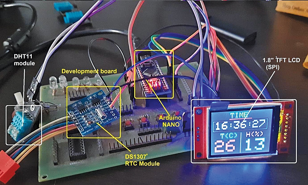
The system combines a DHT (digital humidity and temperature) sensor for environmental readings with an RTC module (DS1307) for timekeeping. Data and time are continuously displayed on the TFT screen with multicoloured graphics and a user-friendly interface. The Arduino reads sensor values and time data at regular intervals, updating the display every few seconds. Fig. 1 shows the prototype with a snapshot of the TFT display.

This compact, cost-effective, and accurate system is well-suited for smart homes, laboratories, greenhouses, and educational use. It also offers scope for expansion into data logging or wireless transmission for IoT-based applications. Table 1 lists the complete Bill of Materials.

| Table 1: Bill of Materials | |
| Components | Quantity |
| Arduino Nano (MOD1) | 1 |
| DHT 11 sensor (S1) | 1 |
| RTC module (MOD2) | 1 |
| TFT display (MOD3) | 1 |
| USB cable | 1 |
Circuit and Working
Fig. 2 shows the circuit diagram of the real-time data monitoring system using a TFT display. It is built around an Arduino Nano board (MOD1), DHT11 sensor (S1), RTC module (MOD2), TFT display (MOD3), and a few other components.
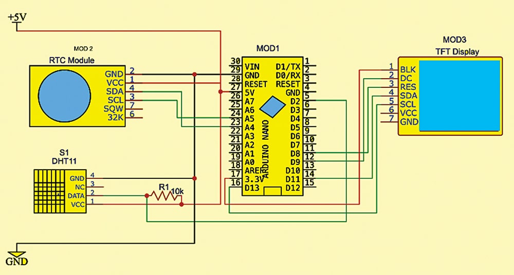
The DHT11 sensor module has three pins: Vcc, GND, and Out. The Vcc pin is connected to the 5V output of the Arduino board, the GND pin is connected to the common ground, and the output pin is connected to the Arduino’s digital pin D2. A 10k pull-up resistor is connected between the output pin and Vcc, as recommended in the DHT sensor datasheet.
The RTC module has four pins: Vcc, GND, SDA, and SCL. Here, the Vcc pin is connected to 5V from the Arduino, while the SDA and SCL pins are connected to Arduino pins A4 (SDA) and A5 (SCL), respectively.
The TFT LCD module has nine interfacing pins, which are connected to the Arduino Nano board as shown in Table 2.
| Table 2: Connections between TFT LCD and Arduino Nano | |
| TFT LCD Pin | Arduino Nano Pin |
| Vcc | 5V |
| Gnd | Gnd |
| LED/BL | 3.3V |
| CS | D10 |
| RST | D8 |
| DC | D9 |
| SDA | D11 |
| SCK | D13 |
The system displays the current room temperature and humidity along with the real-time clock on the TFT display in a clear and user-friendly format. The RTC module (DS1307) communicates with the Arduino using the I²C protocol and provides accurate real-time data in the HH:MM:SS format. This time information is continuously updated and displayed at the top of the TFT screen, ensuring access to the correct time.
The DHT11 sensor is a digital smart sensor that operates on a single-wire protocol, directly providing calibrated digital outputs for both temperature and humidity. The Arduino acts as the main controller, reading data from the DHT11 sensor at intervals of about two seconds. It processes the values and updates the display with the current temperature in degrees Celsius (°C) and relative humidity in percentage (%RH).
By combining data from both the RTC and DHT11 sensors, the Arduino ensures that the TFT display presents real-time temperature, humidity, and clock information simultaneously. This integration makes the system compact, reliable, and efficient, providing a cost-effective way to monitor and display environmental conditions continuously.
Arduino Code

EFY++ CONTENT: ACCESS TO THIS CONTENT IS FREE! BUT YOU NEED TO BE A REGISTERED USER.