

The AI vision assistant camera is a smart device for image recognition and interpretation. Powered by AI, it analyses images from user-defined prompts and generates clear, meaningful descriptions. By combining hardware experimentation with advanced AI, the device enables hobbyists to explore vision intelligence in practical ways.
Compact yet powerful, it captures images with its onboard camera, sends them to OpenAI through API calls, and performs actions via programmable button functions. These buttons can be configured for tasks such as solving mathematical problems, translating languages, or generating image summaries. The device also supports OCR (optical character recognition), image-based translation, and other modes of information extraction.

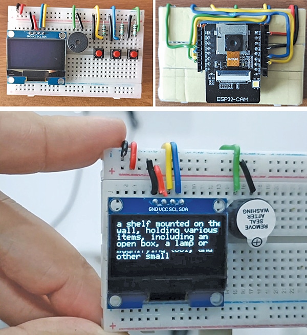
The system is centred around the ESP32-CAM module with an OV2640 camera, which serves as the primary component for capturing images. These images are processed via the OpenAI API, and the analysed results are displayed on an SSD1306 OLED screen. User interaction is facilitated through buttons that allow functions such as capturing images and triggering AI processing. Fig. 1 shows the author’s prototype, and the required components for building the device are listed in the Bill of Materials table.

| Bill of Materials | |
| Components | Quantity |
| ESP32-cam board | 1 |
| HS13L03B2C01, OLED display | 1 |
| Breadboard | 1 |
| Buzzer | 1 |
| Push-to-on switch (SW1-SW3) | 3 |
| Resistor (R1-R3) | 3 |
| USB FTDI adaptor | 1 |
| 3.3V battery | 1 |
Circuit and Working
Fig. 2 shows the circuit diagram of the AI vision assistant camera. The circuit uses the ESP32-CAM (U1) as the main controller for both image processing and task execution. An OLED display, HS13L03B2C01, with an I²C interface (U2) connected via SDA (IO14) and SCL (IO15) pins, is powered by 3.3V to present outputs such as text, translations, or image descriptions.
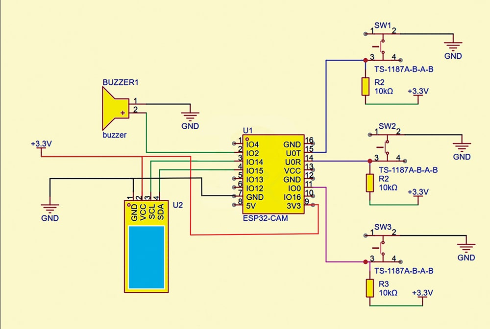
A buzzer is connected to IO4 of the ESP32-CAM, providing audio feedback or alerts during operations such as button presses or task completion. Additionally, three push buttons (SW1, SW2, SW3), each connected through a TS-1187A tactile switch with a 10kΩ pull-down resistor to 3.3V, are wired to GPIO pins IO2, IO12, and IO13. These buttons trigger different functions: SW1 for image capture/OCR, SW2 for translation or image summarisation, and SW3 for a custom AI task, such as solving mathematical problems.
The system operates with a 5V supply powering the ESP32-CAM core, while the 3.3V line supports the peripherals, including the OLED, buzzer, and push buttons.
Software

EFY++ CONTENT: ACCESS TO THIS CONTENT IS FREE! BUT YOU NEED TO BE A REGISTERED USER.